domingo, 21 de marzo de 2010

Synchronous Digital Hierarchy (SDH or SONET)

The introduction of any new technology is usually preceded by much hyperbole and rhetoric. In many cases, the revolution predicted never gets beyond this. In many more, it never achieves the wildly over optimistic growth forecasted by market specialists - home computing and the paperless office to name but two. It is fair to say, however, by whatever method you use to evaluate a new technology, that synchronous digital transmission does not fall into this category. The fundamental benefits to be gained from its deployment by PTOs seem to be so overwhelming that, bar a catastrophe, the bulk of today's plesiochronous transmission systems used for high speed backbone links will be pushed aside in the next few years. To quote Dataquest:, "It has been claimed by many industry experts that the impact of synchronous technology will equal that of the transition from analogue to digital technology or from copper to fibre optic based transmission."
For the first time in telecommunications history there will be a world-wide, uniform and seamless transmission standard for service delivery. Synchronous digital hierarchy (SDH) provides the capability to send data at multi-gigabit rates over today's single-mode fibre-optics links. This first issue of Technology Watch looks at synchronous digital transmission and evaluates its potential impact. Following issues of TW will look at customer oriented broad-band services that will ride on the back of SDH deployment by PTOs. These will include:
  • Frame relay
  • SMDS (Switched Multi-Megabit Data Service)
  • ATM (asynchronous transfer mode)
  • High speed LAN services such as FDDI
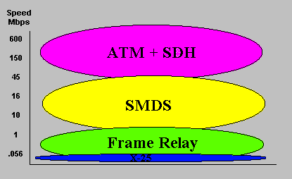
Figure 1 shows the relationship between these technologies and services.
Figure 1 - The Relationship Between Services

Overview

The use of synchronous digital transmission by PTOs in their backbone fibre-optic and radio network will put in place the enabling technology that will support many new broad-band data services demanded by the new breed of computer user. However, the deployment of synchronous digital transmission is not only concerned with the provision of high-speed gigabit networks. It has as much to do with simplifying access to links and with bringing the full benefits of software control in the form of flexibility and introduction of network management.
In many respects, the benefits to the PTO will be the same as those brought to the electronics industry when hard wired logic was replaced by the microprocessor. As with that revolution, synchronous digital transmission will not take hold overnight, but deployment will be spread over a decade, with the technology first appearing on new backbone links. The first to feel the benefits will be the PTOs themselves, as demonstrated by the technology's early uptake by many operators including BT. Only later will customers directly benefit with the introduction of new services such as connectionless LAN-to-LAN transmission capability.
According to one market research company it will take until the mid or late 1990s before 70% of revenue for network equipment manufacturers will be derived from synchronous systems. Remembering that this is a multi-billion $ market, this constitutes a radical change by any standard (Figure 2).
Users who extensively use PCs and workstations with LANs, graphic layout, CAD and remote database applications are now looking to the telecommunication service suppliers to provide the means of interlinking these now powerful machines at data rates commensurable with those achieved by their own in-house LANs. They also want to be able to transfer information to other metropolitan and international sites as easily and as quickly as they can to a colleague sitting at the next desk.
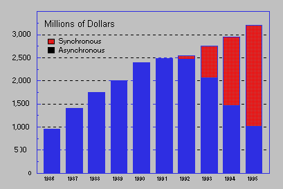
Figure 2 - European Revenue Growth of Transmission Equipment

Plesiochronous Transmission.

Digital data and voice transmission is based on a 2.048Mbit/s bearer consisting of 30 time division multiplexed (TDM) voice channels, each running at 64Kbps (known as E1 and described by the CCITT G.703 specification). At the E1 level, timing is controlled to an accuracy of 1 in 1011 by synchronising to a master Caesium clock. Increasing traffic over the past decade has demanded that more and more of these basic E1 bearers be multiplexed together to provide increased capacity. During this time rates have increased through 8, 34, and 140Mbit/s. The highest capacity commonly encountered today for inter-city fibre optic links is 565Mbit/s, with each link carrying 7,680 base channels, and now even this is insufficient.
Unlike E1 2.048Mbit/s bearers, higher rate bearers in the hierarchy are operated plesiochronously, with tolerances on an absolute bit-rate ranging from 30ppm (parts per million) at 8Mbit/s to 15ppm at 140Mbit/s. Multiplexing such bearers (known as tributaries in SDH speak) to a higher aggregate rate (e.g. 4 x 8Mbit/s to 1 x 34Mbit/s) requires the padding of each tributary by adding bits such that their combined rate together with the addition of control bits matches the final aggregate rate. Plesiochronous transmission is now often referred to as plesiochronous digital hierarchy (PDH).
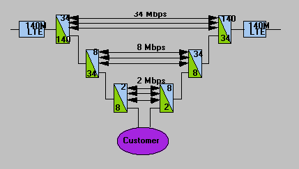
Figure 3 - A typical Plesiochronous Drop & Insert
Because of the large investment in earlier generations of plesiochronous transmission equipment, each step increase in capacity has necessitated maintaining compatibility with what was already installed by adding yet another layer of multiplexing. This has created the situation where each data link has a rigid physical and electrical multiplexing hierarchy at either end. Once multiplexed, there is no simple way an individual E1 bearer can be identified in a PDH hierarchy, let alone extracted, without fully demultiplexing down to the E1 level again as shown in Figure 3.
The limitations of PDS multiplexing are:
  • A hierarchy of multiplexers at either end of the link can lead to reduced reliability and resilience, minimum flexibility, long reconfiguration turn-around times, large equipment volume, and high capital-equipment and maintenance costs.
  • PDH links are generally limited to point-to-point configurations with full demultiplexing at each switching or cross connect node.
  • Incompatibilities at the optical interfaces of two different suppliers can cause major system integration problems.
  • To add or drop an individual channel or add a lower rate branch to a backbone link a complete hierarchy of MUXs is required as shown in figure 3.
  • Because of these limitations of PDH, the introduction of an acceptable world-wide synchronous transmission standard called SDH is welcomed by all.

Synchronous Transmission

In the USA in the early 1980s, it was clear that a new standard was required to overcome the limitations presented by PDH networks, so the ANSI (American National Standards Institute) SONET (synchronous optical network) standard was born in 1984. By 1988, collaboration between ANSI and CCITT produced an international standard, a superset of SONET, called synchronous digital hierarchy (SDH).
US SONET standards are based on STS-1 (synchronous transport signal) equivalent to 51.84Mbit/s. When encoded and modulated onto a fibre optic carrier STS-1 is known as OC-1. This particular rate was chosen to accommodate a US T-3 plesiochronous payload to maintain backwards compatibility with PDH. Higher data rates are multiples of this up to STS-48, which is 2,488Gbit/s.
SDH is based on an STM-1 (155.52Mbit/s) rate, which is identical to the SONET STS-3 rate. Some higher bearer rates coincide with SONET rates such as: STS-12 and STM-4 = 622Mbit/s, and STS-48 and STM-16 = 2.488Gbit/s. Mercury is currently trialing STM-1 and STM-16 rate equipment.
SDH supports the transmission of all PDH payloads, other than 8Mbit/s, and ATM, SMDS and MAN data. Most importantly, because each type of payload is transmitted in containers synchronous with the STM-1 frame, selected payloads may be inserted or extracted from the STM-1 or STM-N aggregate without the need to fully hierarchically de-multiplex as with PDH systems.
Further, all SDH equipment is software controlled, even down to the individual chip, allowing centralised management of the network configuration, and largely obviates the need for plugs and sockets. A future SDH network could look like Figure 4.
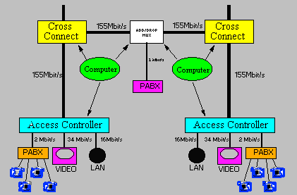
Figure 4- An Example Future SDH Digital Network

Benefits of SDH Transmission

SDH transmission systems have many benefits over PDH:
  • Software Control allows extensive use of intelligent network management software for high flexibility, fast and easy re-configurability, and efficient network management.
  • Survivability. With SDH, ring networks become practicable and their use enables automatic reconfiguration and traffic rerouting when a link is damaged. End-to-end monitoring will allow full management and maintenance of the whole network.
  • Efficient drop and insert. SDH allows simple and efficient cross-connect without full hierarchical multiplexing or de-multiplexing. A single E1 2.048Mbit/s tail can be dropped or inserted with relative ease even on Gbit/s links.
  • Standardisation enables the interconnection of equipment from different suppliers through support of common digital and optical standards and interfaces.
  • Robustness and resilience of installed networks is increased.
  • Equipment size and operating costs are reduced by removing the need for banks of multiplexers and de-multiplexers. Follow-on maintenance costs are also reduced.
  • Backwards compatibly will enable SDH links to support PDH traffic.
  • Future proof. SDH forms the basis, in partnership with ATM (asynchronous transfer mode), of broad-band transmission, otherwise known as B-ISDN or the precursor of this service in the form of Switched Multimegabit Data Service, (SMDS).

Conclusions

The introduction of synchronous digital transmission in the form of SDH will eventually revolutionise all aspects of public data communication from individual leased lines through to trunk networks. Because of the state-of-the-art nature of SDH and SONET technology, there are extensive field trials taking place in 1992 throughout the world prior to introduction in the 1993 - 1995 time scale.
There is still a lack of understanding of the ramifications of the introduction of SDH within telecommunications operations. In practice, the use of extensive software control will impact positively all parts of the business. It is not so much a question of whether the technology will be taken up, but when.
Introduction of SDH will lead to the availability of many new broad-band data services providing users with increased flexibility. It is in this area where confusion reigns with potential technologies vying for supremacy. These will be discussed in future issues of Technology Watch.
Importantly for PTOs, SDH will bring about more competition between equipment suppliers designing essentially to a common standard. One practical effect could be to force equipment prices down, brought about by the larger volumes engendered by access to world rather than local markets. At least one manufacturer is currently stating that they will be spending up to 80% of their SDH development budgets on management software rather than hardware. Such was the situation in the computer industry in the early 1980s. Not least, it will have a great impact on such issues as staffing levels and required personal skills of personnel within PTOs.
SDH deployment will take a great deal of investment and effort since it replaces the very infrastructure of the world's core communications networks. But it must not be forgotten that there are still many issues to be resolved.
The benefits to be gained in terms of improving operator profitability, and helping them to compete in the new markets of the 1990s, are so high that deployment of SDH is just a question of time.


Hernandez Caballero Indiana M. CI: 15.242.745
Asignatura: SCO
Fuente:http://images.google.co.ve/imgres?imgurl=http://www.gare.co.uk/technology_watch/images/sdh4.gif&imgrefurl=http://www.gare.co.uk/technology_watch/sdh.htm&usg=__GIHKzmjHZisMDOScJFUIx5DQWgk=&h=277&w=421&sz=7&hl=es&start=2&um=1&itbs=1&tbnid=12nRG6Iu8VZUCM:&tbnh=82&tbnw=125&prev=/images%3Fq%3DSDH%26um%3D1%26hl%3Des%26client%3Dfirefox-a%26rls%3Dorg.mozilla:es-ES:official%26channel%3Ds%26tbs%3Disch:1


What is Gigabit Ethernet?

Gigabit Ethernet is an extension of the highly successful 10 Mbps (10BASE-T) Ethernet and 100 Mbps (100BASE-T) Fast Ethernet standards for network connectivity (see Figure 2). IEEE has given approval to the Gigabit Ethernet project as the IEEE 802.3z Task Force, and the specification is expected to be complete in early 1998. There have been more than 200 individuals representing more than 50 companies involved in the specification activities to date.


Figure 2

Figure 2. Functional elements of Gigabit Ethernet technology.
Gigabit Ethernet is fully compatible with the huge installed base of Ethernet and Fast Ethernet nodes. The original Ethernet specification was defined by the frame format and support for CSMA/CD (Carrier Sense Multiple Access with Collision Detection) protocol, full duplex, flow control, and management objects as defined by the IEEE 802.3 standard. Gigabit Ethernet will employ all of these specifications.
In short, Gigabit Ethernet is the same Ethernet that managers already know and use, but 10 times faster than Fast Ethernet and 100 times faster than Ethernet. It also supports additional features that accommodate today's bandwidth-hungry applications and match the increasing power of the server and desktop.


The Benefits of Gigabit Ethernet To support increasing bandwidth needs, Gigabit Ethernet incorporates enhancements that enable fast optical fiber connections at the physical layer of the network. It provides a tenfold increase in MAC (Media Access Control) layer data rates to support video conferencing, complex imaging and other data-intensive applications.
Gigabit Ethernet has the advantage of being compatible with the most popular networking architecture, Ethernet. Since its introduction in the early 1980s, Ethernet deployment has been rapid, quickly overshadowing networking connection choices such as Token Ring and ATM.


Key Advantages of Gigabit Ethernet

Gigabit Ethernet compatibility with Ethernet preserves investments in administrator expertise and support staff training, while taking advantage of user familiarity. There is no need to purchase additional protocol stacks or invest in new middleware. Just as 100 Mbps Fast Ethernet provided a low-cost, incremental migration from 10 Mbps Ethernet, Gigabit Ethernet will provide the next logical migration to 1000 Mbps bandwidth.

By 1996, according to IDC research projections, more than 80 percent of installed connections were Ethernet. The dominance of Ethernet is expected to continue beyond 1998, particularly as this compatible and scalable standard moves to gigabit speeds. In addition to a wider choice of products and vendors, this market dominance has brought with it a steady decrease in Ethernet hardware costs (see Figure 3).


Figure 3

Figure 3

Figure 3

Figure 3. Ethernet and Fast Ethernet products have shown steady cost reductions over time. Similar trends are anticipated for Gigabit Ethernet products. (Source: Dell Oro Group)
As Information Technology (IT) departments adopt Fast Ethernet, and eventually Gigabit Ethernet to enhance network performance to support robust desktop needs, they will see:

  • Increased network performance levels, including traffic localization and high-speed cross segment movement
  • Increased network scaleability — it will be easier to add and manage more users and "hungrier" applications
  • Decreased overall costs over time


Fast Ethernet Paves the Way to Gigabit Ethernet The proliferation of Intel Pentium®, Pentium® Pro and Pentium® II processor-based desktops in corporate networks, combined with new bandwidth-intensive operating systems and applications, has already influenced many LAN decision makers to migrate to Fast Ethernet. First proposed in 1993, Fast Ethernet is quickly becoming the high-speed technology for today's LANs and corporate desktop users. It enjoys broad multi-vendor support and brisk migration interest among customers.
Intel believes Gigabit Ethernet will enjoy rapid deployment, following the proven track records of Ethernet and Fast Ethernet. It addresses the bandwidth dilemma without requiring costly protocol changes.
Most important, Gigabit Ethernet promises to efficiently match the power of high-performance PCs that increasingly populate the LAN. As businesses go to these more powerful processors, they need a high-performance infrastructure all the way from the desktop to the backbone.


How Will Gigabit Ethernet be Deployed? Gigabit Ethernet deployment scenarios will most likely mirror the model of Fast Ethernet, though the new technology is expected to become standardized and implemented at an even faster rate. The transformation will be driven by several factors:

  • The established popularity of Ethernet and the compatibility offered by Gigabit Ethernet solutions
  • The experience and momentum already garnered in bringing Fast Ethernet to market
  • The commitment and expertise of the vendors involved
Deployment Scenarios
Scenario 1: Gigabit Ethernet will be switched and routed at the network backbone with switch-to-switch connections. The first installations will use optical fiber for long connections between buildings and copper links for shorter connections.


Scenario 1

Scenario 1
Scenario 2: Next, switch-to-server deployments will be implemented to boost access to critical server resources. Many 100 Mbps switches contain module slots that will accommodate Gigabit Ethernet so they will be able to uplink to server connections at 1000 Mbps.


Scenario 2

Scenario 2
Scenario 3: Finally, as desktop costs come down and user network demands increase, Gigabit Ethernet will move to the workgroup and desktop level; Gigabit Ethernet switches will enter the backbone as older switches are replaced and Gigabit Ethernet will take over the switch fabric. This evolution will be driven by the increasing installation of 100 Mbps PCs as the standard desktop, and the migration of power users to switched 100 Mbps, and switch-to-switch uplink connections will advance to 1000 Mbps. At this time, customers will see gigabit links that are compliant with the installed base of UTP Category 5 cabling. (Over copper media, the Gigabit Ethernet Standards Committee has proposed two distance options: 25 meters and 100 meters.)


Scenario 3

Scenario 3


Figure 4

Figure 4. Strong growth is predicted for Gigabit Ethernet products. (Source: IDC #12382, Nov. 96)


Intel's Plans for Gigabit Ethernet Intel is uniquely positioned in the emerging market for Gigabit Ethernet products. With strengths in chip design, technology development and volume manufacturing, Intel will be able to give customers best-of-class products and comprehensive solutions at the best value.
Intel has established itself as a leader in the transition to Fast Ethernet, with its family of Fast Ethernet desktop, server and mobile adapters, print servers, hubs and switches. The PCI bus for Intel architecture PCs and servers is tailor-made for today's power users. A 32-bit PCI implementation already pumps out data in the multi-hundred megabits range. In the future, a 64-bit PCI bus will easily handle Gigabit Ethernet throughput at the desktop.
Adaptive Technology is one example of how Intel's silicon expertise has helped to boost network performance and extend the product life of both network adapters and switches. That same expertise will keep Intel at the forefront of Gigabit chip speed enhancements, as well.
Ongoing relationships with key industry leaders — Cisco, Microsoft and others — reflect Intel's commitment to extending and supporting industry standards by working with these leaders to provide end-to-end, desktop-to-campus solutions. This cooperation will assure compatibility with Gigabit Ethernet products that emerge from other vendors.
Intel intends to bring the same commitment to Gigabit Ethernet solutions as it has to Fast Ethernet, initially focusing on uplinks to the backbone, switch-to-switch links, and switch-to-server connections. The strategy will be extended as needed to other high-bandwidth networking products, in order to provide complete, cost-effective solutions, from the desktop to the backbone.


Hernandez Caballero Indiana M. CI: 15.242.745
Asignatura: SCO
Fuente:http://images.google.co.ve/imgres?imgurl=http://www.intel.com/network/connectivity/resources/doc_library/tech_brief/pix/gigabit_ethernet_fig1.gif&imgrefurl=http://www.intel.com/network/connectivity/resources/doc_library/tech_brief/gigabit_ethernet.htm&usg=__LuFuk8i3jhDtKFNvALBeP4ecAeI=&h=270&w=410&sz=10&hl=es&start=18&um=1&itbs=1&tbnid=JpUReJ_rIZeIkM:&tbnh=82&tbnw=125&prev=/images%3Fq%3DGigabit%2BEthernet%26um%3D1%26hl%3Des%26client%3Dfirefox-a%26sa%3DG%26rls%3Dorg.mozilla:es-ES:official%26channel%3Ds%26tbs%3Disch:1


Core DWDM network protection


Figure 1 shows a typical DWDM link
Solutions DWDM Fig1
Figure 1: Typical unprotected DWDM link

Some of the wavelengths in the link may be sections of a larger single wavelength network such as a Sonet/SDH ring or IP mesh. Services transported over this wavelength (T1 service in the diagram), may be protected by the network's inherent recovery mechanism. Other wavelengths within the link may carry high-speed point-to-point traffic as a "leased line" service. Services of this type may be combined to use one DWDM wavelength. These are called "sub-lambda services". If a single service utilizes a dedicated DWDM wavelength, it is referred to as a "wavelength service". As can be seen from the figure above, clients of these services are not protected and any failure in the DWDM link will interrupt their traffic.

The high availability of these critical services is achieved through the use of redundant resources (equipment and fiber) and protection systems that perform automatic protection switching (APS) when failure of a working resource is detected. There are several solutions for protection of DWDM networks. The choice of solution depends on the redundant resources being used as well as the required protection scheme. Resource redundancy may vary according to various factors: cost and geographical limitations, detection and repair time, etc. The protection scheme is determined by deployment considerations. For example, paths in which there are large length differences between the working and protection links may require a "dual-ended" protection scheme, to avoid problems associated with latency imbalance.

Lynx provides the following solutions for DWDM network protection:
  • Optical channel/path protection
  • DWDM line protection
  • 1:n DWDM tributary protection
  • In-line amplifier protection
Optical Channel /Path Protection
This mechanism provides end-to-end protection of an entire DWDM channel, from one client site to the other. It is based on complete channel redundancy, including fibers, inline equipment and transponder line-cards that interface with the CPE.
Figure 2 shows an example of optical channel protection.
Solutions DWDM Fig2

Figure 2: Optical channel/path protection

In some optical channels, which contain transport equipment and interconnecting fibers, failures can be detected by monitoring the optical signal. In such cases, performing 1+1 single-ended protection can be done by fiber protection systems. For other protection schemes, such as dual-ended protection, Lynx provides special in-band signaling solutions. In cases where the transport equipment does not support shut-off during failure, but sends AIS signals instead, failure detection must be done at the protocol level. Lynx offers Optical Failure Monitoring (OFM) modules, capable of detecting failures in all these situations. Lynx has also developed a unique technology, LynxSense™, to ensure that protection switches will indeed switch immediately when required.

Some Lynx protection systems allow users to carry extra traffic, thereby improving the utilization of the network redundancy. This extra traffic is carried over the protection channel while both channels are operational.

DWDM Line Protection
In some cases, deploying a redundant DWDM line may be more cost-effective than using several redundant channels: this depends on the number of active channels in a DWDM link that require protection (e.g., not segments of SDH/Sonet rings), and the amount of in-line transport equipment. Assuming that the terminal transponders can be protected through a 1+N protection scheme (Figure 3), and that the passive Mux/Demux is highly reliable, carriers may choose to protect only the DWDM line. Figure 4 shows such an application.

Solutions DWDM Fig3


  • One direction depicted (client Tx)


  • Upon failure of the blue transponder the backup transpoder is configures to Blue and the client and network fibers previously connected to the blue transponder are switched to the backup one.
Figure 3: 1-N protection scheme


Solutions DWDM Fig4
Figure 4: DWDM line protection
As in the case of 1+1 single-ended optical channel protection, simple DWDM lines (such as clear fiber) can be protected by fiber protection systems. DWDM lines where in-line equipment such as EDFA is used, may be subjected to noisy optical signals during failures. Optical power monitoring may not be sufficient, and Lynx's Optical Failure Monitor (OFM) for DWDM lines is recommended for effective and comprehensive failure detection.

Compared to electro-optical (OEO) protection mechanisms, optical switching is a far more cost-effective way of protecting DWDM lines. Electro-optical protection requires double multiplexing/demultiplexing, and N termination and protection systems (where N is the number of potential wavelengths over the line).

In-line Amplifier Protection
In some cases, due to cost or geographical limitations, the DWDM link cannot be redundantly diverse; and the protection solutions described above cannot be used. In other cases, where some form of link protection exists, there may be long lag times in identifying and repairing in-line amplifiers, leaving the network vulnerable for unacceptably long periods. In such cases, carriers can use Lynx's EDFA systems to protect some of the in-line amplifiers locally, providing an option for immediate recovery while repair crews are dispatched. Lynx 1:n (2+1) add-on protection systems are used to protect an EDFA node (two EDFAs, one in each direction) with the use of a single spare EDFA. A special EDFA failure monitoring module, built into the protection system, is capable of detecting EDFA failures—including those in which the EDFA continues to transmit optical power.
Figure 5 shows an example of EDFA protection.
Solutions DWDM Fig5
Figure 5: In-line amplifier (EDFA) protection


Hernandez Caballero Indiana M. CI: 15.242.745
Asignatura: SCO
Fuente:http://images.google.co.ve/imgres?imgurl=http://www.lynxpn.com/data/uploads/Figures/Solutions%2520DWDM%2520Fig1.jpg&imgrefurl=http://www.lynxpn.com/content.asp%3FpageId%3D52&usg=__ucvYuOHkQUZVeUOUhINzckNd2dw=&h=362&w=651&sz=56&hl=es&start=14&um=1&itbs=1&tbnid=-buQ2RKUsynJ3M:&tbnh=77&tbnw=138&prev=/images%3Fq%3DSONET%2Bwith%2BDWDM%26um%3D1%26hl%3Des%26client%3Dfirefox-a%26sa%3DG%26rls%3Dorg.mozilla:es-ES:official%26channel%3Ds%26tbs%3Disch:1


Time Division Multiplexing (TDM) versus Wavelength Division Multiplexing (WDM)

Ultrahigh-speed photonic networks capable of accommodating the increase in Internet data traffic will form the infrastructure of the information society of the next generation. There are two types of multiplexing schemes to accommodate such large amount of information: wavelength division multiplexing (WDM), which multiplexes signals using lightwaves with different wavelengths, and time division multiplexing (TDM), which multiplexes signals in different bit slots in the time domain. In WDM systems, transmitters and receivers in each channel work independently, and thus WDM allows signals with different format to be accommodated in one network. In this sense, WDM is an "analog" multiplexing scheme. In constrast, TDM requires sophisticated signal processing employing, for example, multiplexers, demultiplexers, clock recovery, and network synchronization. Nevertheless it supports "digital" multiplexing, where synchronized high speed signals are processed together. Optical TDM (OTDM) makes the most of these advantages in the optical domain and is another important technique for the construction of photonic networks in addition to the development of highspeed signal processing.

Fig. 1 TDM versus WDM

1.28 Tbit/s OTDM signal transmission


Fig. 2 Optical transmission systems and signal pulse interval.

Figure 2 shows the improvement in the TDM transmission speed in backbone terrestial optical transmission systems in Japan. The transmission speed has increased from 400 Mbit/s to 2.4 Gbit/s and 10 Gbit/s. With the help of WDM, the capacity can be increased further. Work on a 40 Gbit/s system is currently in progress and it will be installed in the backbone system in the near future. This system benefits from the development of high speed electronic devices.
The next research target is ultrahigh-speed OTDM transmission with a bit rate of 160 Gbit/s or even 1 Tbit/s, where highspeed signals are multiplexed in the optical domain alone, without the need for any electronic devices. OTDM transmission operates in a regime far beyond the capability of electronic devices. In this regime ultra short pulses are transmitted with pulse widths of pico second to a few hundred femto second order. This would be impossible without the development of advanced technologies such as the generation of femto-second pulses, higher-order dispersion compensation, and all-optical demultiplexers.
Fig. 3 Experimental setup for 1.28 Tbit/s OTDM signal transmission.
Figure 3 shows our setup for a 1.28 Tbit/s-70 km OTDM transmission experiment, which was successfully achieved for the first time in the world. A 3 ps, 10 GHz regeneratively and harmonically mode-locked fiber laser operating at 1.544 mm was used as the original pulse source. The output laser pulse was intensity-modulated at 10 Gbit/s and the pulse train was coupled into a dispersion-flattened dispersion decreasing fiber. This realized adiabatic soliton compression to less than 200 fs. We incorporated a phase modulation technique that compensated for the third- and fourth-order dispersion of the transmission fiber. The pre-chirped 10 GHz pulse train was optically multiplexed to 640 Gbit/s by using a planar lightwave circuit (PLC). We obtained a 1.28 Tbit/s signal by polarization multiplexing two 640 Gbit/s pulse trains.
Fig. 4 Optical signal waveform in 1.28 Tbit/s OTDM signal transmission.

Fugure 4 shows the input and output data patterns. Clean 640 Gbit/s signals were obtained in each channel. The pulse broadening after 70 km transmission was only 20 fs. We obtained a  bit error rate of 10-9 was achieved for all the channels.


Hernandez Caballero Indiana M. CI: 15.242.745
Asignatura: SCO
Fuente:http://images.google.co.ve/imgres?imgurl=http://www.nakazawa.riec.tohoku.ac.jp/English/reserch/2-1.jpg&imgrefurl=http://www.nakazawa.riec.tohoku.ac.jp/English/reserch/re02.html&usg=__N5b5CWvKjJ_Hl2mnmhPO6FN3gBc=&h=1017&w=987&sz=211&hl=es&start=4&um=1&itbs=1&tbnid=NZvmH6CZR3w1YM:&tbnh=150&tbnw=146&prev=/images%3Fq%3DTDM%2Band%2BWDM%2BCompared%26um%3D1%26hl%3Des%26client%3Dfirefox-a%26rls%3Dorg.mozilla:es-ES:official%26channel%3Ds%26tbs%3Disch:1


Marking SDH and DWDM packet friendly

Back in 1993, I wrote about the advances taking pace in fiber optic technologies and optical amplifiers. At that time, technology development was principally concerned with improving transmission distances using optical amplifier technology and increasing data rates. These optical cables a single wavelength and hence provided provided a single data channel.Wide area traffic in the early 1990s was principally dominated by Public Switched Telephone Network (PSTN) telephony traffic as this was well before the explosion in data traffic caused by the Internet. When additional throughput was required, it was relatively simple to lay down additional fibres in a terrestrial environment. Indeed, this became standard procedure to the extent that many fibres were laid in a single pipe with only a few being used or lit as it was known. Unlit fibre strands were called dark fibre. For terrestrial networks when increasing traffic demanded additional bandwidth on a link, it was simple job to simply add additional ports the appropriate SDH equipment and light up an additional dark fibre.
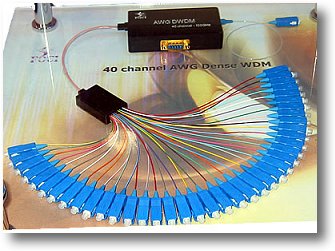
Wave Division Multiplexing (Picture credit: photeon)
In undersea cables adding additional fibres to support traffic growth was not so easy so the concept of Wave Division Multiplexing (WDM) came into common usage for point to point links (the laboratory development of WDM actually went back to the 1970s). The use of WDM enabled transoceanic carriers to upgrade the bandwidths of their undersea cables without the need to lay additional cables which would cost multiple billions of Dollars.
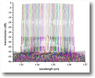
As shown in the picture, a WDM based system uses multiple wavelengths thus multiplying the available bandwidth by the number wavelengths that could be supported. The number of wavelengths that could be used and the data rate on each wavelength were limited by the quality of the optical fibre that was being upgraded and the current state-of-the-art of the optical termination electronics. Multiplexers and de-multiplexers at either end of the cable aggregated and split the combined data into separate channels by converted to and from electrical signals.
A number of WDM technologies or architectures were standardised over time. In the early days, Course Wavelength Division Multiplexing (CWDM) was relatively proprietary in nature and meant different things to different companies. CWDM combines up to 16 wavelengths onto a single fibre and uses an ITU standard 20nm spacing between the wavelengths of 1310nm to 1610nm. With CWDM technology, since the wavelengths are relatively far apart compared to DWDM, the are generally relatively cheap.
One of the major issues at the time was that Erbium Doped Fibre Amplifiers (EDFAs) as described in optical amplifiers could not be utilised due to the wavelengths selected or the frequency stability required to be able de-multiplex the multiplexed signals
In the late 1990s there was an explosion of development activity aimed at deriving benefit of the concept of Dense Wavelength Division Multiplexing (DWDM) to be able to utilise EDFA amplifiers that operated in 1550nm window. EDFAs will amplify any number of wavelengths modulated at any data rate as long as they are within its amplification bandwidth.
DWDM combines up to 64 wavelengths onto a single fibre and uses an ITU standard that specifies 100GHz or 200GHz spacing between the wavelengths, arranged in several bands around 1500-1600nm. With DWDM technology, the wavelengths are close together than used in CWDM, resulting in the multiplexing equipment being more complex and expensive than CWDM. However, DWDM allowed a much higher density of wavelengths and enabled longer distances to be covered through the use of EDFAs. DWDM systems were developed that could deliver tens of Terabits of data over a single fibre using up to 40 or 80 simultaneous wavelengths e.g. Lucent 1998.
I wouldn't claim to be an expert in the subject, but I would expect that in dense urban environments or over longer runs where access is available to the fibre runs, it is considerably cheaper to install additional runs of fibre than to install expensive DWDM systems. An exception to this would be a carrier installing cables across a continent. If dark fibre is available then it's an even simpler decision.
Although considerable advances were taking place at optical transport with the advent of DWDM systems, existing SONET and SDH standards of the time were limited to working with a single wavelength per fibre and were also limited to working with single optical links in the physical layer. SDH could cope with astounding data rates on a single wavelengths, but could not be used with emerging DWDM optical equipment.
Optical Transport Hierarchy
This major deficiency in SDH / SONET led to further standards development initiatives to bring it "up to date". These are known as the Optical Transport Network (OTN) working in an Optical Transport Hierarchy (OTH) world. OTH is the same nomenclature as used for PDH and SDH networks.
The ITU-T G.709 (released between 1999 – 2003) standard Interfaces for the OTN is a standardised set of methods for transporting wavelengths in a DWDM optical network that allows the use of completely optical switches known as Optical Cross Connects that does not require expensive optical-electrical-optical conversions. In effect G.709 provides a service abstraction layer between services such as standard SDH, IP, MPLS or Ethernet and the physical DWDM optical transport layer. This capability is also known as OTN/WDH in a similar way that the term IP/MPLS is used. Optical signals with bit rates of 2.5, 10, and 40 Gbits/s were standardised in G.709 (G.709 overview presentation) (G.709 tutorial).
The functionality added to SDH in G.709 is:
  • Management of optical channels in the optical domain
  • Forward error correction (FEC) to improve error performance and enable longer optical spans
  • Provides standard methods for managing end to end optical wavelengths
Other SDH extensions to bring SDH up to date and make it 'packet friendly'
Almost in parallel with the development of G.709 standards a number of other extensions were made to SDH to make it more packet friendly.
Generic Framing Procedure (GFP): The ITU, ANSI, and IETF have specified standards for transporting various services such as IP, ATM and Ethernet over SONET/SDH networks. GFP is a protocol for encapsulating packets over SONET/SDH networks.
Virtual Concatenation (VCAT): Packets in data traffic such as Packet over SONET (POS) are concatenated into larger SONET / SDH payloads to transport them more efficiently.
Link Capacity Adjustment Scheme (LCAS): When customers' needs for capacity change, they want the change to occur without any disruption in the service. LCAS a VCAT control mechanism, provides this capability.
These standards have helped SDH / SONET to adapt to an IP or Ethernet packet based world which was missing in the original protocol standards of the early 1990s.
Next Generation SDH (NG-SDH)
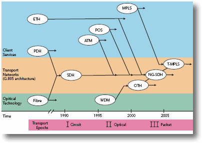
If a SONET or SDH network is deployed with all the extensions that make it packet friendly is deployed it is commonly called a Next Generation SDH (NG-SDH). The diagram below, shows the different ages of SDH concluding in the latest ITU standards work called T-MPLS ( I cover T-MPLS in: PBT – PBB-TE or will it be T-MPLS?
Transport Ages (Picture credit: TPACK)
Multiservice provisioning platform (MSPP)
Another term in widespread use with advanced optical networks is MSPP.
SONET / SDH equipment use what are known as add / drop multiplexers (ADMs) to insert or extract data from an optical link. Technology improvements enabled ADMs to include cross-connect functionality to manage multiple fibre rings and DWDM in a single chassis. These new devices replaced multiple legacy ADMs and also allow connections directly from Ethernet LANs to a service provider's optical backbone. This capability was a real benefit to Metro networks sitting between enterprise LANs and long distance carriers.
There are many variant acronyms in use as there are equipment vendors:
  • Multiservice provisioning platform (MSPP): includes SDH multiplexing, sometimes with add-drop, plus Ethernet ports, sometimes packet multiplexing and switching, sometimes WDM.
  • Multiservice switching platform (MSSP): an MSPP with a large capacity for TDM switching.
  • Multiservice transport node (MSTN): an MSPP with feature-rich packet switching.
  • Multiservice access node (MSAN): an MSPP designed for customer access, largely via copper pairs carrying Digital-Subscriber Line (DSL) services.
  • Optical edge device (OED): an MSSP with no WDM functions.
This has been an interesting post in that it has brought together many of the technologies and protocols discussed in the previous posts, in particular SDH, Ethernet and MPLS and joined them to optical networks. It seem strange to say on one hand that the main justification of deploying converged Next Generation Networks (NGNs) based on IP is to simplify existing networks and hence reduce costs, but then consider the complexity and plethora of acronyms and standards associated with that!


Hernandez Caballero Indiana M. CI: 15.242.745
Asignatura: SCO
Fuente:http://images.google.co.ve/imgres?imgurl=http://www.gare.co.uk/images/dwdm1.jpg&imgrefurl=http://technologyinside.com/2007/03/&usg=__pdHii1qgthKmbJKQcoqlAJxPSeo=&h=251&w=335&sz=29&hl=es&start=6&um=1&itbs=1&tbnid=s43ED1hkm8W1IM:&tbnh=89&tbnw=119&prev=/images%3Fq%3DWavelength%2BDivision%2BMultiplexing%26um%3D1%26hl%3Des%26client%3Dfirefox-a%26sa%3DG%26rls%3Dorg.mozilla:es-ES:official%26channel%3Ds%26tbs%3Disch:1


CWDM, DWDM & ROADM

In a typical fiber optic network, the data signal is transmitted using single light pulse at either 1310 nm or 1550 nm wavelengths.  Historically, the way to increase the capacity of a single fiber is to increase the bit rate of the signal (1 Mbps to 10 Mbps to 100 Mbps).  Throughout the last 30 years, optical systems have increased their capacity regularly, allowing for bandwidth upgrades that outpaced the growth in bandwidth demands.

Primarily driven by Ethernet and packet-based services, the need for bandwidth has exploded. Even mid-sized network operators are demanding multiple 10 Gbps pipes to accommodate large increases for growing and diverse applications such as surveillance, ITV, and data-center connections. This growth requires transport that is flexible and scalable
Wavelength division multiplexing (WDM) is now a cost-effective, flexible and scalable technology for increasing capacity of a fiber network. WDM architecture is based a simple concept – instead of transmitting a single signal on a single wavelength, transmit multiple signals, each with a different wavelength. Each remains a separate data signal, at any bit rate with any protocol, unaffected by other signal on the fiber.
Wave Division Multiplexing

CWDM and DWDM

There are two types of WDM: Coarse and Dense Wavelength Division Multiplexing (CWDM and DWDM).
CWDM uses a wide spectrum and accommodates eight channels.  This wide spacing of channels allows for the use of moderately priced optics, but limits capacity.  CWDM is typically used for lower-cost, lower-capacity, shorter-distance applications where cost is the paramount decision criteria.
DWDM systems pack 16 or more channels into a narrow spectrum window very near the 1550 nm local attenuation minimum.  Decreasing channel spacing requires the use of more precise and costly optics, but allows for significantly more scalability.  Typical DWDM systems provide 1-44 channels of capacity, with some new systems, offering up to 80-160 channels. DWDM is typically used where high capacity is needed over a limited fiber resource or where it is cost prohibitive to deploy more fiber.

ROADM and FOADM

As with most transport systems, there are requirements to add and drop traffic along ring and tapered networks.  WDM systems support two types of add/drop Fixed and Reconfigurable Optical Add/Drop Multiplexers (FOADM and ROADM).
FOADMs are based on simple static fibers that permit add/drop of predefined wavelengths. These systems are fully integrated and manageable and provide a fine balance of features and cost.
ROADMs add the ability to remotely switch traffic from a WDM system at the wavelength layer. While more expensive than FOADMs, ROADMs are used in application where traffic patterns are not fully known or change frequently.
The key features and benefits of WDM include:
  • Protocol and Bit Rate Agnostic – wavelengths can accept virtually any services
  • Fiber Capacity Expansion – WDM adds up to 160X bandwidth to a single fiber
  • Hi Cap/Long Haul and Lo Cap/Short Haul Applications – CWDM and DWDM provide price performance for virtually any network
  • Remotely Provisionable – ROADMs provide the flexibility to change with changing network requirements
WDM Network

Hernandez Caballero Indiana M. CI: 15.242.745
Asignatura: SCO
Fuente:http://images.google.co.ve/imgres?imgurl=http://www.lightriver.com/uploadfiles/images/product/Sol-WDM-Arch.jpg&imgrefurl=http://www.lightriver.com/index.php%3Fp%3Dcwdm_dwdm_roadm&usg=__DYkgWA7vStr5sZetZifUWXpmO0o=&h=408&w=763&sz=159&hl=es&start=5&um=1&itbs=1&tbnid=muSaAnYMxpGxeM:&tbnh=76&tbnw=142&prev=/images%3Fq%3DWavelength%2BDivision%2BMultiplexing%26um%3D1%26hl%3Des%26client%3Dfirefox-a%26sa%3DG%26rls%3Dorg.mozilla:es-ES:official%26channel%3Ds%26tbs%3Disch:1